Measuring RF Attenuation Through a Wall
Attenuation is known as signal loss. The primary cause of attenuation is distance as the signal travels away from the transmitter1. Objects like walls also cause attenuation.
When creating a Wi-Fi design for a walled environment, we care to know the wall attenuation values. These values are used for design input2. This is because not all walls are equal. The make of walls will vary. Some may be dry wall, double dry wall, dry wall as a façade over some material, brick, concrete, or other materials.
Below are some of my notes on how to measure the attenuation of a wall.
The items needed:
- A device to generate Wi-Fi.
- Examples include your phone with a hotspot enabled, a USB powered WLAN Pi3 in hotspot mode, or an Enterprise grade AP with a battery pack.
- Ideally use a generating device that you can control the transmit power and channel. This is for the sake of consistency across your measurements.
- A device to measure Wi-Fi.
Here is a process to follow for a particular wall:
-
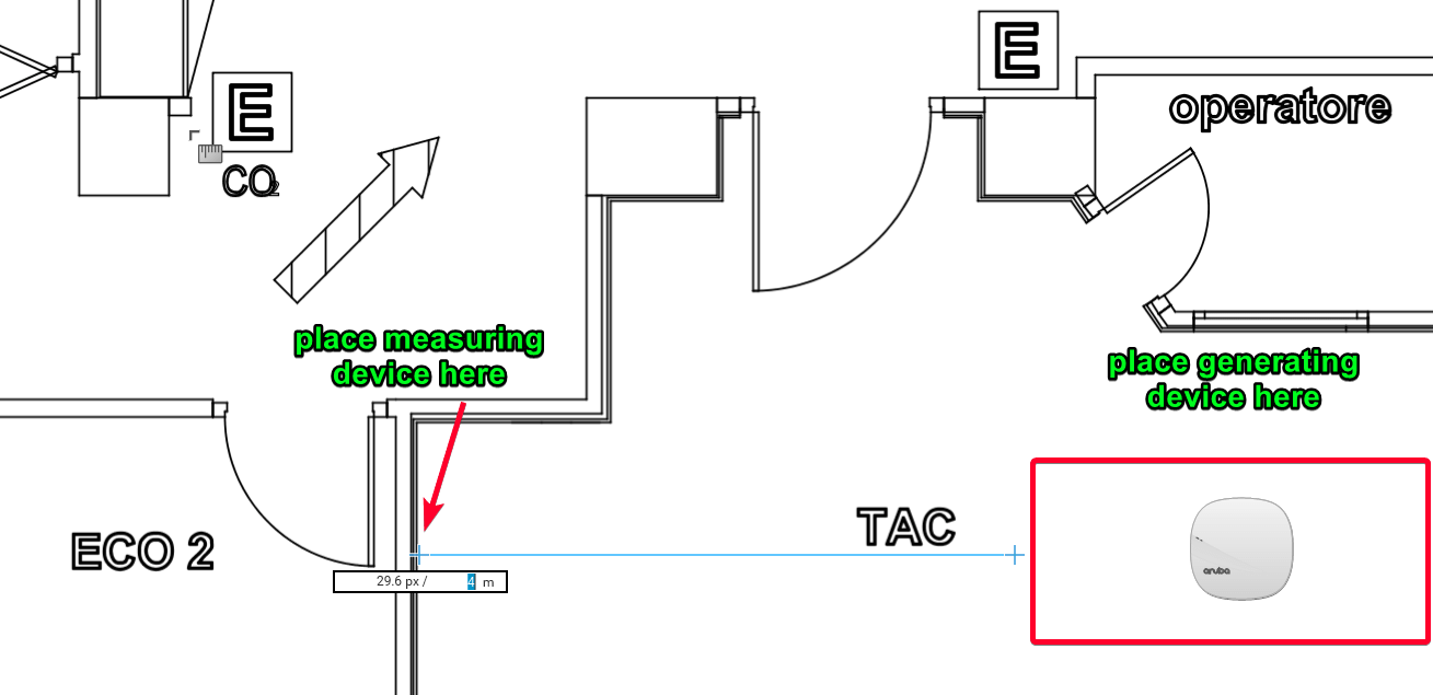
Place your Wi-Fi generating device at least 4 meters6 (12-15 feet for you Imperial folks) away from the wall you are measuring. There should be nothing between the device generating Wi-Fi and the wall.
Example:
-
If you can control the scanning channel on your measuring device, set it to scan on only the channel that your generating device is using.
-
Point the ‘ear’7 of the measuring device towards the generating device on the near side of the wall. There should be direct line of sight between both the generating and measuring devices. Do not stand between them. Stand (or sit) to the side.
-
Take several sets of measurements and determine the average on the near side of the wall. You could refer to these as X. Make note of these values.
-
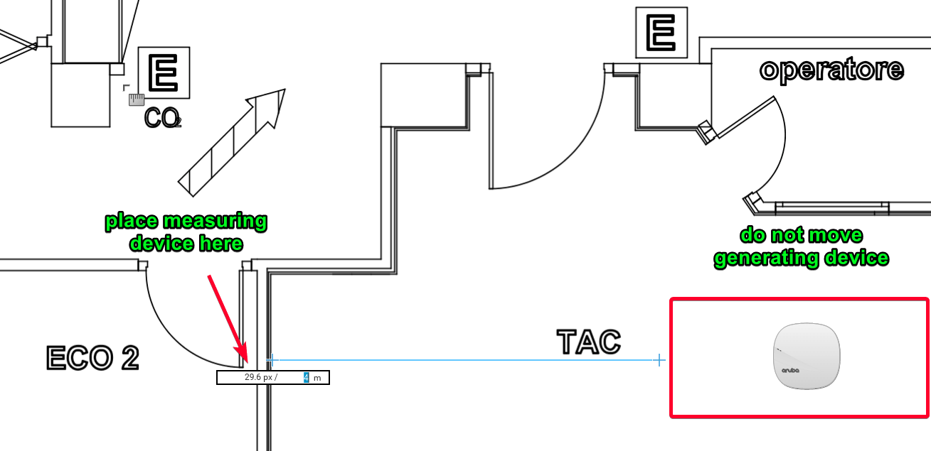
Move the measuring device directly to the other side of the wall. Similar to the previous measurements, point the ‘ear’ of the measuring device towards the generating device. If you can, try to make sure nothing inside the wall is skewing the results.
Example:
-
Take several sets of measurements and determine the average on the far side of the wall. You could refer to these as Y. Make note of these values.
-
X - Y = Wall Attenuation
-
Document!
Changelog
- 2020/09/24: minor updates, added example images
Thanks to Mark Brasacchio and Ryan Stewart for reading drafts of this.
-
This is also known as Free Space Path Loss (FSPL) ↩
-
If we use unchecked default values for walls, our design output could have unexpected real world results. ↩
-
https://play.google.com/store/apps/details?id=com.arubanetworks.arubautilities&hl=en_US ↩
-
4 meters or greater is to minimize FSPL impact on wall measurements. We want to measure the wall, not FSPL. ↩
-
This is where the antenna element is on your measuring device. Keep the orientation of the measurement device the same on both sides of the wall. ↩